Electronic Ignition System
CJ750 IGNITION SYSTEM
Wrote by Vendor – MH MOTO WORLD.
Original writer – Tim O’connor.
Ver. 1.12 (1.11 update is very important)
Ver. 1.13 (a little bit update)
Ver. 1.14 (a notification)
Thanks for purchase this set. And after receive such a lot of reports, I can finally write this guide for all my customers.
So, before you setup this set to your CJ750. PLEASE READ EVERYTHING AGAIN & AGAIN! And make sure you fully understand everything. If met any stupid things, check this guide at first, or email me: metillca@hotmail.com, or xyb0311@hotmail.com
Ver. 1.1 special thanks for Mr. Tim O’connor from U.S.
OK, from the very start. You will receive this set:
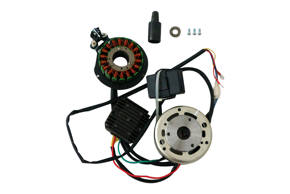
You will receive:
1. new stator and rotor.
2. new rectifier.
3. electronic ignition.
4. 3 screws and washer.
5. stator nut.
6. wires.
P.S.: wires color may vary. I’ll mark the wires for which point before I send to you. Some rectifier came with battery charger wire. I’ll mark for you. BUT don’t ask me “I NEED THAT WIRE!”. If the rectifier maker made this wire, you will get it. Otherwise, you won’t. If you do that, I may deny your orders.
At first. Please:
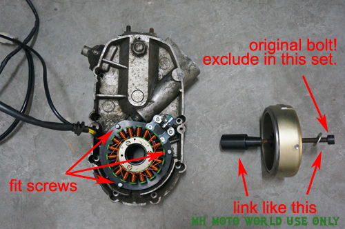
1. before install. Please remove: Si Commutator (rectifier) , stator/rotor, and Adjuster. Fully remove! But DON'T THROW the original ROTOR BOLT! This bolt was easy broke when you remove the rotor. Be careful!
2. from now on, you need to install the stator:
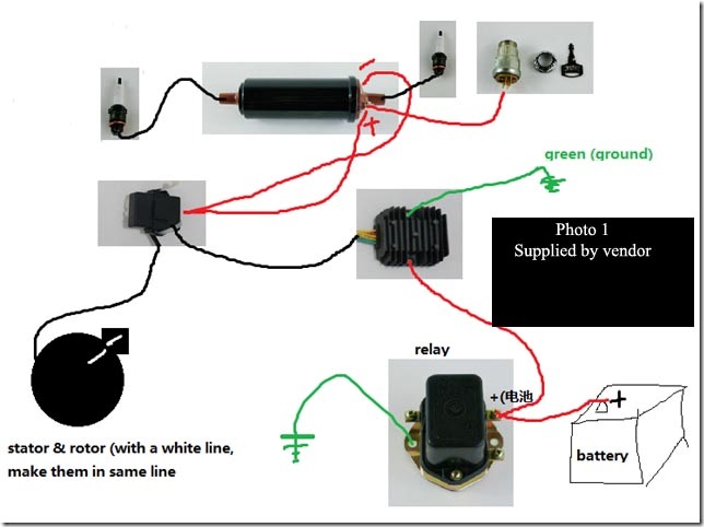
And now, quote from Mr. O’connor:
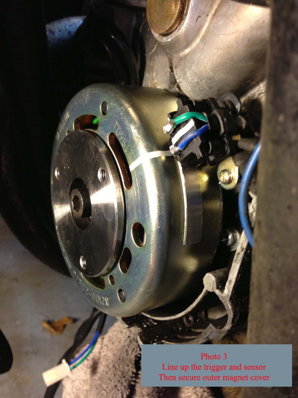
The only thing I found confusing or missing from this diagram is that you need to know how to set the timing. Line up the white lines on the unit housing with the sender with the engine at TDC (Top Dead Center). I was confused about this because some other units I have installed on other engines wanted the sender lined up at six degrees before or after.
This is the peep hole in the side of the engine showing the flywheel markings indicating TDC. It should reasonably closely line up with the ZERO ( -0 ) marking. (THAT’S VERY IMPORTANT!)
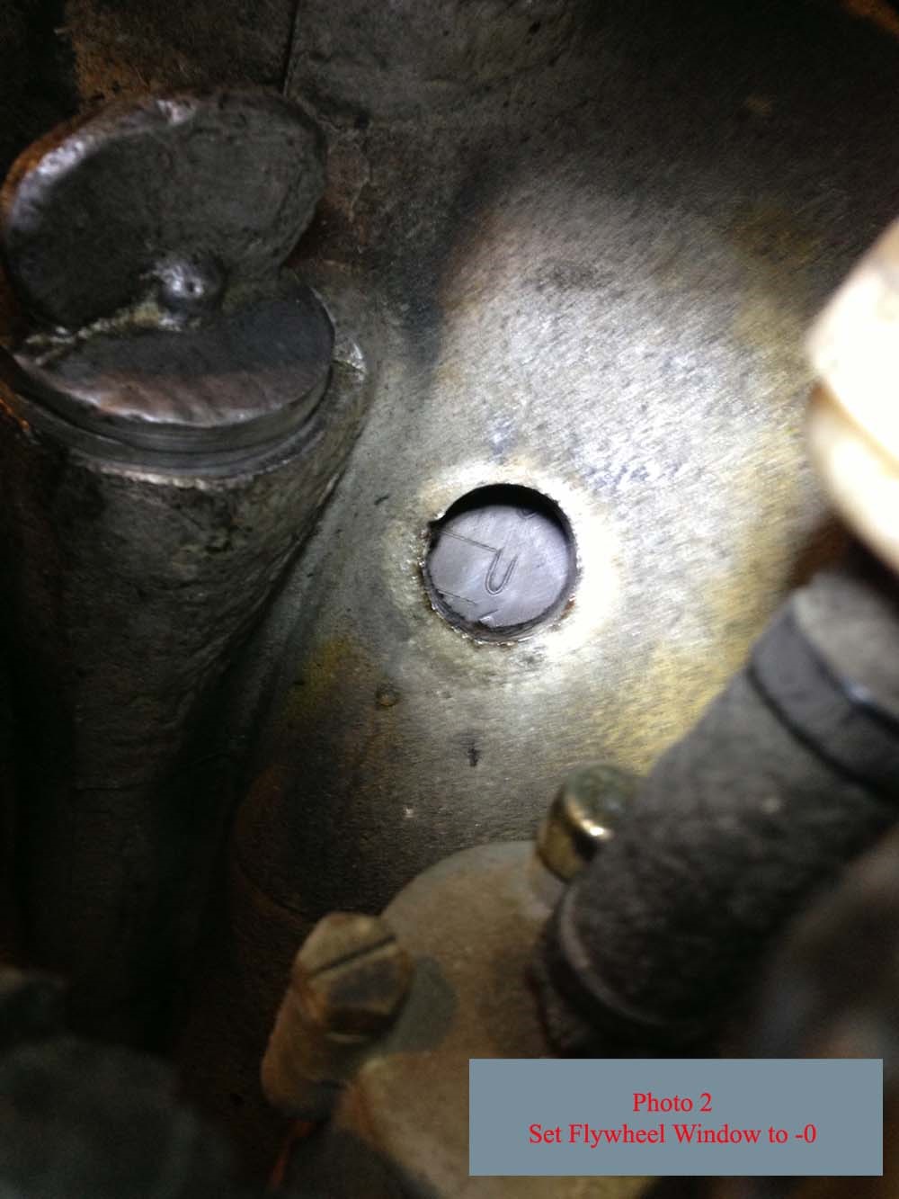
Assuming the flywheel is on TDC (Zero) the unit is now aligned and ready to be tightened down. (make sure the white line to the white line!!!!)
Till now, you nearly installed everything. But under the reports, MAKE SURE THE FRONT ENGINE COVER can closed all the parts. Mr. O’connor seems met small problems, and need modify his cover and house. See below:
Photo Four.
Here is my only significant problem.
I found that my front engine cover did not leave enough room for the new unit. When I put it on the sensor trigger it the cover leaving a gouge (see photo) and removed the timing alignment.
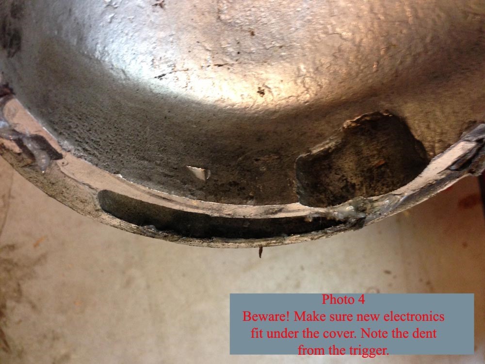
Photo Five.
To fix the cover problem I used a wheel grinder to cut away some aluminum in the cover to make room for the new unit.
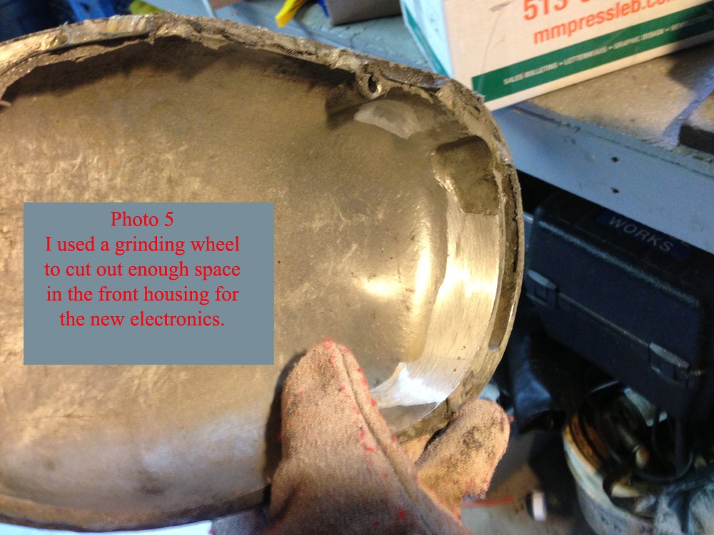
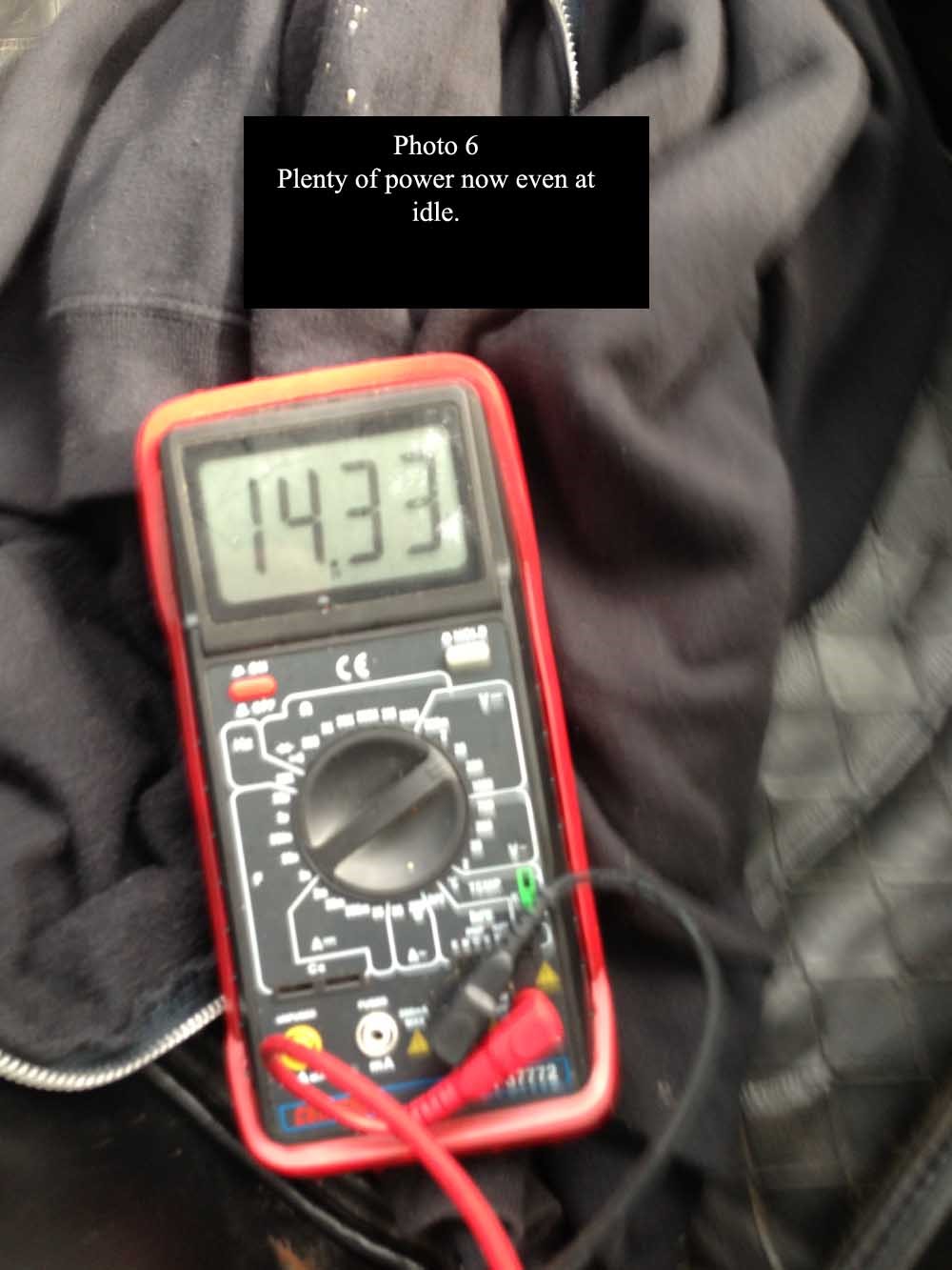
Photo Six.
After removing the old wiring (yeah!) and starting the bike the charging system give plenty of power even at low idle. The timing is great and works nicely throughout the entire speed and power range.
Tips / Notes:
I used locktite semi-perm on the rotor bolt . It seems to me that the way this is mounted does not give a lot of surface area for holding things in place long term so I wanted a little extra grip.
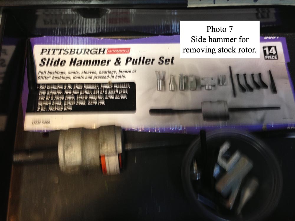
Photo 7.
This is the slider hammer I use to remove the BMW style rotors. It is not expensive and has exactly the correct size threads for the CJ750. I purchased this one from Harbor Freight.
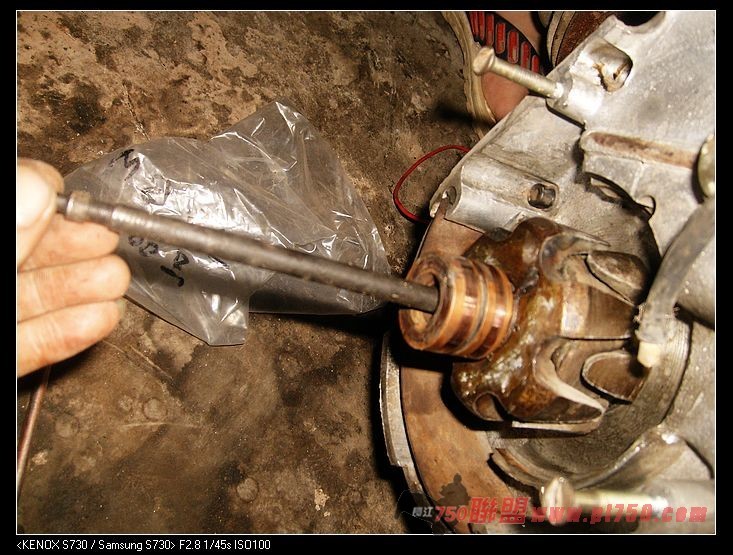
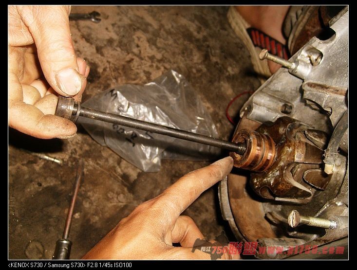
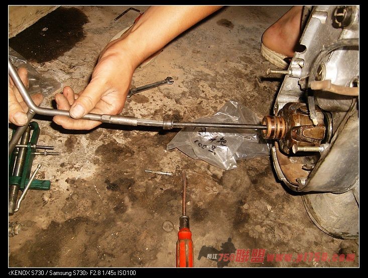
1.12 update: usually, we put the clutch release long pin into the rotor’s hole, and then, use the bolt screw in and screw out… The rotor removed! See photo below photo 7.
OK, if you didn’t met anything like that. Just forget it. Now we need to setup the electric box. See photo:

The photo tell you the same story like photo 1. But the important thing is the new rectifier (in photo top right.). Don’t put it in narrow space. Make sure it can be cool when riding.

1.11 update (very important):
Some one find the top right small piece on the stator was damaged during shipping, it didn’t break, But on the wrong place of the stator. So, need do some job for it.. If you receive a one really bad damaged, don’t do anything on it. Just email me, and will resend a new small one for you.
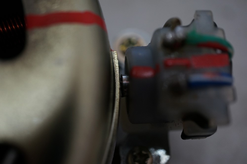
So, I show you the distance if some one also met this problem.
The point on that piece should be NEARLY touch the rotor upper piece (but didn’t touch the rotor!!!). That was just under the red mark. And this higher is 1.5 mm.
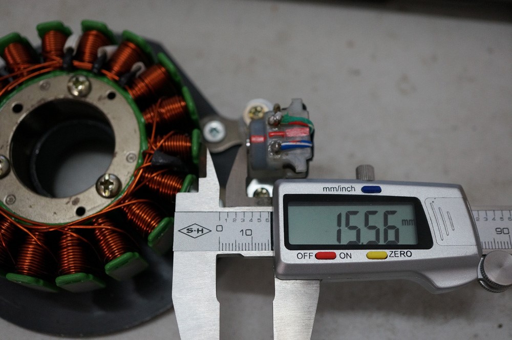
I remove the rotor. You can see the point should be about 15.5mm to the coil. So, if you cannot reduce it in above photo. Just remove the rotor, and reduce it aways from the coil about 15.5mm
*Due to I cannot put the ruler into the gap. So, have 0.06mm +/-. I don’t think that was a big problem here.
1.12 update:
If you can use another battery jump start your bike. But the bike’s battery doesn’t working: fully charge your bike’s battery!!!
If you cannot kick start your bike: strong and fast kick! Kick again!
Also, 1.11 update is very IMPORTANT! The small pieces on the stator may left the original place during shipping. So, use your hand reduce it. Make it NEARLY touch the rotor like the photo!
Usually, if nothing broke, you won’t met the bike cannot start problems. So, just try aboves.
1.14: Very important notification:
If you modified your bike: please change back to original. Like coil, relay, flywheel or something like that.
About the new rectifier:
If you got: plug+red wire+black wire: the black wire is ground. You can like it to bike frame. If not stable, you can use another wires, like the red wire to battery's +. Black wire to battery's -. (but keep the original wire to relay and ground)
If you got: plug+red wire+green wire: after installed but not stable, please left green wire don't touch anything. Or just cut it off from the end of rectifier.
At the end:
You can now remove the old distributor. Because of the ignition point is useless. The new electroinc ignition was fully programed, with a small cpu inside. It will be change time delay by RPM, which the old ignition point won’t do that. So, now, your bike can ride a bit faster (about 10KM/H).
For some reason, you can also remove your battery, if you always use the kick starter. Because of the set provide about 300W when it working. So, you needn’t care about the battery charge. Your bike have enough power when it working.
DON’T do anything stupid before you fully understand how to install! Don’t try to modify it if you haven’t enough experience. If you cannot setup like the photo, just read the guide again, or, contact with me (I always reply in 24 hours, just remember that). You may got a very very rare model CJ750, that make you confused and cannot setup the full set into the engine house.
I cannot guarantee this set can work on M72 or other model bikes. So, if you want to try, just do that but I cannot provide any help. Just for 12V system bikes only.
FIN.
Remark: if you can translate to Franch, German, Spainish or other languages, please help (Korean and Japanese please contact me at first, I can provide Chinese version that can help you translate more easily). I’ll be very happy add your name into the special thanks. This guide was totally free. Just for CJ750 fans. For all the bikers. If you want to past it on some forum, just do that, but please don’t remove MH MOTO WORLD and Mr. Tim O’connor. Tks.